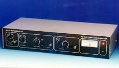
Single phase analogue lock-in amplifier
Please contact us for further information on this product.

Single phase analogue lock-in amplifier
Please contact us for further information on this product.
Scitec Instruments Model 410 is a single phase analogue lock-in amplifier. It is suitable for making amplitude and phase measurements.
Lock-in amplifiers are used to measure the amplitude and phase of small AC signals in the presence of much larger noise levels. They are widely used to recover small optical signals such as those encountered in spectroscopy and studies of fluorescence and luminescence. However, they also have applications in many other fields including electronics and cryogenics where they can be used in component characterisation, bridge networks and to measure the resistance of superconductors.
The output from a lock-in amplifier is a DC voltage proportional to the amplitude of the input signal but with the noise removed. It is also a function of the relative phase difference between the input signal and the associated reference signal. This property allows lock-in amplifiers to be used for measuring the phase properties of the input signal as well.
Scitec Instruments lock-in amplifiers are available as both single phase and dual phase instruments. Single phase lock-in amplifiers have a single demodulator and can be used to make both amplitude and phase measurements. However a manual set-up procedure is required both initially and following any phase change of the output signal. Dual phase lock-in amplifiers have two demodulators which operate with a 90° phase separation. In-phase and out-of-phase components are measured simultaneously which simplifies the process of making amplitude and phase measurements. In addition the Model 420 has circuitry for calculating the vector magnitude from the output of the two demodulators. Both the Model 410 and Model 420 instruments can be used to make measurements of the input signal at both the first and second harmonic of the reference signal.
A key figure of merit used for lock-in amplifiers is dynamic reserve. The dynamic reserve of a lock-in amplifier is defined as the ratio of the noise to signal that is allowed before saturation occurs. The dynamic reserve for the Model 410 is 60dB, allowing an input signal buried in noise 1000 times larger to be recovered.
The input signal channel amplifies the input signal to a level suitable for the demodulator. High performance, low-noise, broad-band amplifiers are used throughout. The input circuitry can accept a differential or single-ended input via the front panel signal input BNC.
The output of the signal input stage is processed using a very high bandwidth demodulator to recover the input signal.
The output from the demodulator is passed through a first order low pass filter and then amplified before output via a front panel BNC.
The datasheet for the Model 410 and Model 420 lock-in amplifiers is available in pdf format: