Dual phase analogue lock-in amplifier
Please contact us for further information on this product.
Dual phase analogue lock-in amplifier
Please contact us for further information on this product.
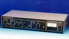
Scitec Instruments Model 420 is a dual phase analogue lock-in amplifier. It is suitable for making amplitude and phase measurements.
Scitec Instruments lock-in amplifiers are available as both single phase and dual phase instruments. Single phase lock-in amplifiers have a single demodulator and can be used to make both amplitude and phase measurements. However a manual set-up procedure is required both initially and following any phase change of the output signal. Dual phase lock-in amplifiers have two demodulators which operate with a 90° phase separation. In-phase and out-of-phase components are measured simultaneously which simplifies the process of making amplitude and phase measurements. In addition the Model 420 has circuitry for calculating the vector magnitude from the output of the two demodulators. The Model 420 instruments can be used to make measurements of the input signal at both the first and second harmonic of the reference signal.
A key figure of merit used for lock-in amplifiers is dynamic reserve. The dynamic reserve of a lock-in amplifier is defined as the ratio of the noise to signal that is allowed before saturation occurs. The dynamic reserve for the Model 420 is 60dB, allowing an input signal buried in noise 1000 times larger to be recovered.
The input signal channel amplifies the input signal to a level suitable for the demodulator. High performance, low-noise, broad-band amplifiers are used throughout. The input circuitry can accept a differential or single-ended input via the front panel signal input BNC.
The output of the signal input stage is processed using two very high bandwidth demodulators each operating 90° apart from each other to produce the X and Y signals.
The X and Y outputs from the demodulators are passed through two first order low pass filters and then amplified. The X and Y signals are combined to produce R, the modulus signal, where R=(X2+Y2)1/2 before output via a front panel BNC.
The datasheet for the Model 410 and Model 420 lock-in amplifiers is available in pdf format: